prettyprint

顯示具有 Raspberry Pi 標籤的文章。 顯示所有文章

2022年6月23日 星期四

在Raspberry Pi 3B+安裝FreeBSD 13.1 並實作WiFi Client/Access Point/Wireless Router等功能

     本實驗在Raspberry Pi 3B+硬體上安裝FreeeBSD 13.1系統,用來實現並測試當作WiFi Client 、 Access Point(AP)與Wireless Router的功能,三種模式如下圖所示:


因為FreeBSD尚未支援Raspberry Pi內建無線網卡的Driver,所以本次實驗以外加一片usb網卡(TP-Link TL-WN725N)來測試。

👉安裝FreeBSD 13.1系統在Raspberry Pi 3B+上

從FreeBSD官網下載image檔案:FreeBSD-13.1-RELEASE-arm64-aarch64-RPI.img.xz

下載Raspberry Pi Imager(https://downloads.raspberrypi.org/imager/imager_latest.exe)燒錄FreeBSD image到SD(註1)上,過程可參閱文末成果影片連結。

FreeBSD使用Raspberry Pi硬體,螢幕輸出的介面有兩種: primary為TTL Serial, Secondary 為Vodeo(HDMI介面),本實驗使用USB-UART介面接到筆電的USB上,開啟PuTTY Serial Port,如下圖,Raspberry Pi pinout可參閱https://pinout.xyz/。[RPI: Gnd(6), TX(8), RX(10)]

  • 系統root內定的password為root

本實驗使用的TP-Link TL-WN725N在FreeBSD下的driver 為rtwn,使用指令dmesg查閱,如下圖所示:

但使用內定參數實測後,網路存取速度異常慢,調整設定,載入kdlload wlan_amrr模組或設定dev.rtwn.0.ratectl=0,即可獲得良好的網路存取速度,可在/boot/loader.conf設定如下:
dev.rtwn.0.ratectl=0
wlan_amrr_load="YES"


👉設定成為WiFi Client使用:

  • 在/etc/rc.conf設定
wlans_rtwn0="wlan0"
ifconfig_wlan0="WPA SYNCDHCP"
create_args_wlan0="country TW"

  • 增設/etc/wpa_supplicant.conf檔案,內容填入
ctrl_interface=/var/run/wpa_supplicant
ctrl_interface_group=wheel
network={
        ssid="your ssid"
scan_ssid=1
key_mgmt=WPA-PSK
psk="your passwd"
}
更改正確的ssid與psk
重新啟用系統後即可連至WiFi網路


👉設定成為Access Point(Bridge)使用:
Raspberry Pi wifi介面改成hostap mode,再將有線網路介面ue0與無線網路介面wlan0,加入到bridge members中。如上圖,終端無線設備(手機、筆電等)連到 Raspberry Pi AP後,即可將無線網路橋接到ISP Router連到Internet。終端無線設備屬於同一個網段,本實驗的例子為192.168.1.0/24。
  • 在/etc/rc.conf設定如下
#WLAN hostap mode
wlans_rtwn0="wlan0"
create_args_wlan0="wlanmode hostap -apbridge country TW"
hostapd_enable="YES"
# create a bridge
cloned_interfaces="bridge0"
ifconfig_bridge0="inet 192.168.1.61/24 addm ue0 addm wlan0 up"
ifconfig_ue0="up"
ifconfig_wlan0="up"
#enable geteway(net.inet.ip.forwarding)
gateway_enable="YES"

  • 在/etc/hostapd.conf下設定如下
interface=wlan0
debug=1
ctrl_interface=/var/run/hostapd
ctrl_interface_group=wheel
ssid=myAP_SSID                       #==>改成你的SSID
wpa=2
wpa_passphrase=PassW0rd      #==>改成你的passphrase
wpa_key_mgmt=WPA-PSK
wpa_pairwise=CCMP

重新啟用系統Raspberry Pi即成為無線網路的Access Point。
但在系統重新啟動後,並無法正常使用,bridge0並未將ue0與wlan0加入bridge0的members中。
以dmesg查看driver啟用順序,發現bridge0先啟用後,ue0與wlan0再啟用,推測因此bridge0才無法把加入ue0與wlan0正確加入到bridge0的members中。
以netstat -r 查看 route table並未正確產生

因此把bridge0建立時間延後到啟用local daemon時,再來create bridge並加入ue0與wlan0到members中,步驟如下:
  1. 取消/etc/rc.conf中的下面兩行
    cloned_interfaces="bridge0"
    ifconfig_bridge0="inet 192.168.1.61/24 addm ue0 addm wlan0 up"
  2. 在/etc/rc.local加入
    #!/bin/sh
    br=`ifconfig bridge create`
    ifconfig $br addm ue0 addm wlan0
    dhclient $br
修改後重啟系統即可正常使用AP功能了。

👉設定成為Wireless Router使用:
設定為router模式時,WiFi與有線LAN分別屬於不同網段,因此Raspberry Pi須具備路由器功能。如上圖所示,有線的LAN連接ISP Router為192.168.1.0/24,無線網路為10.10.200.0/24,Raspberry Pi Router無線網路介面設定IP為10.10.200.1。所以Raspberry Pi上需增加NAT(Firewall)、DHCP server與DNS server等功能(DNS server為選項)。
設定步驟如下:

➤DHCP Server使用isc-dhcp時:

執行指令
pkg install -y isc-dhcp44-server
加入hdcp server功能,啟用方式

  1. 在/etc/rc.conf中加入
    dhcpd_enable="YES"
    dhcpd_flags="-q"
    dhcpd_conf="/usr/local/etc/dhcpd.conf"
    dhcpd_ifaces="wlan0"
    dhcpd_withumask="022"
  2. 在/usr/local/etc/dhcpd.conf中加入
    option domain-name "mytest.org";
    default-lease-time 60;
    max-lease-time 72;
    # A slightly different configuration for an internal subnet.
     subnet 10.10.200.0 netmask 255.255.255.0 {
            range 10.10.200.10 10.10.200.20;
            option domain-name-servers 192.168.1.1;
            option routers 10.10.200.1;
            default-lease-time 600;
            max-lease-time 7200;
    }

➤DHCP Server使用dnsmasq時:

執行指令
pkg install -y dnsmasq
  1. 在/etc/rc.conf中加入
    dnsmasq_enable="YES"
  2. 在/usr/local/etc/dnsmasq.conf中加入
    interface=wlan0
    dhcp-range=10.10.200.90,10.10.200.100,255.255.255.0,24h

➤啟用Firewall(NAT)與hostap等功能:

本實驗使用IPFW與IN-Kernel NAT
  • 在/etc/rc.conf設定如下(使用dnsmasq)
ifconfig_ue0="DHCP"
#WLAN WiFi hostap
wlans_rtwn0="wlan0"
create_args_wlan0="wlanmode hostap -apbridge country TW"
ifconfig_wlan0="inet 10.10.200.1 netmask 255.255.255.0"
hostapd_enable="YES"

ifconfig_ue0="up"
ifconfig_wlan0="up"

#Filrewall and NAT enable
firewall_enable="YES"
firewall_nat_enable="YES"
firewall_script="/etc/ipfw.rules"
gateway_enable="YES"

dnsmasq_enable="YES"

  • 在/etc/ipfw.rules下設定如下:

ipfw -q -f flush
cmd="ipfw -q add"
skip="skipto 1000"
pif=ue0
wif=wlan0
ks="keep-state"
good_tcpo="22,25,37,53,80,443,110"
ipfw disable one_pass
ipfw -q nat 1 config if $pif same_ports unreg_only reset
$cmd 005 allow all from any to any via $wif
$cmd 010 allow all from any to any via lo0 # exclude loopback traffic
$cmd 099 reass all from any to any in # reassemble inbound packets
$cmd 100 nat 1 ip from any to any in via $pif # NAT any inbound packets
# Allow the packet through if it has an existing entry in the dynamic rules table
$cmd 101 check-state
# Authorized outbound packets
$cmd 200 $skip tcp from any to any $good_tcpo out via $pif setup $ks
$cmd 210 $skip udp from any to any 53 out via $pif $ks
$cmd 220 $skip icmp from any to any out via $pif $ks
# allow all outbound
$cmd 230 $skip tcp from any to any out via $pif setup $ks
#Authorized inbound packets
$cmd 500 allow icmp from any to me via $pif
$cmd 501 allow tcp from any to me 22 via $pif setup $ks
# otherwise deny
$cmd 999 deny log all from any to any
$cmd 1000 nat 1 ip from any to any out via $pif # skipto location for outbound stateful rules
$cmd 1001 allow ip from any to any

詳細過程可觀看下列影片:


註1:

本次實驗使用不同SD卡安裝系統,若讀者發現系統DISK IO異常,也許可換不同廠牌SD卡試試看。


2022年5月9日 星期一

Raspberry Pi 3 + FreeBSD + ZFS + iSCSI (Part 1)

實驗在Raspberry pi 3 B+上安裝FreeBSD作業系統,啟用ZFS檔案系統,比較ZFS dataset有使用壓縮(Compression)與副本(copies)屬性使用磁碟空間比較。另外建立一個ZFS Volume(Block device)作為iSCSI Target使用。以Windows系統連線iSCSI Target並格式化為NTFS。測試ZFS snapshot, rollback 等功能。 

一、下載Raspberry Pi的FreeBSD OS Image:

從FreeBSD官網下載作業系統映像檔,如下圖所示:

下載檔案:FreeBSD-13.0-RELEASE-arm64-aarch64-RPI.img.xz


二、使用Raspberry Pi Imager安裝作業系統到SD Card上:
  1. 從https://www.raspberrypi.com/software/下載Raspberry Pi Imager:
  2. 安裝FreeBSD Image:
    選用use custom選項,安裝剛剛下載的OS映像檔。

三、設定FreeBSD Static IP, nameserver, 與sshd允許遠端連線:

  1. static IP: 查看網路面卡名稱(ue0),編輯/etc/rc.conf加入
    ipconfig_ue0="inet x.x.x.x netmask x.x.x.x"
    defaultrouter="x.x.x.x"

  2. nameserver:編輯/etc/resolv.conf加入nameserver ip:

  3. sshd:編輯/etc/ssh/sshd_config更改permitRootLogin成yes

四、把外接USB硬碟加入ZFS pool:

啟用ZFS服務:
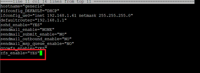
  1. 編輯/etc/rc.conf加入zfs_enable="YES"

  2. 執行service zfs start啟用zfs service
  3. 查看外接USB硬碟設備代號(da0),
    執行zpool create storage da0建立名稱為storage的zfs pool。

五、比較zfs dataset具有compression與copies屬性儲存空間的差異

  1. 分別建立storage/normal, storage/compress與storage/data三個filesystem,

  2. 設定storage/compress具有compression屬性
  3. 設定storage/data具有copies=2屬性,可把資料儲存兩份,增加可靠性
  4. 複製相同的資料到這三個檔案系統,查看使用硬碟空間的差異。


    六、建立iSCSI Target,使用Windows iSCSI Initiator 連線成為自己的硬碟

  1. 建立zfs volume(block device)作為iSCSI Target設備 zfs create -V 25G storage/iscsi01
  2. 編輯/etc/ctl.conf
    更改etc.conf權限,chmod 644 /etc/ctl.conf
    編輯/etc/rc.conf加入ctld_enable="YES"
    啟用service ctld start

  3. 啟用Windows iSCSI Initiator 連線iSCSI Target

  4. 使用Windoes disk managment格式化iSCSI 硬碟

七、zfs snapshot與rollback展示:

2021年8月18日 星期三

Integrate Raspberry Pi, ESP32-CAM , ONVIF compliant cameras and Shinobi Software to build a Video Surveillance System

 實驗目標:

  1. 以Raspberry Pi 3B+架設NVR系統,使用Shinobi free, open source software。
  2. ESP32-CAM串流輸出MPEG video到NVR,儲存在硬碟中。
  3. 使用D-Link DCS-8300LHV2 Wi-Fi ONVIF camera儲存影音到NVR。
  4. 連續錄影與移動偵測錄影。


一、NVR系統架設步驟:
    使用raspberry Pi 3B+板子,使用外接USB硬碟為儲存設備。
  • 下載Raspberry Pi Imager,執行安裝Raspberry Pi OS。
選擇安裝Rapberry Pi OS Lite(32 bit),Write to SD card

  • 設定Rapberry Pi:
    1. 啟用SSH:
      sudo raspi-config
      Interface Options
      SSH


    2. 設定固定IP:
      $ sudo nano /etc/dhcpcd.conf

      #static ip_address=192.168.1.23/24
      #static routers=192.168.1.1
      #static domain_name_servers=192.168.1.1
      取消註解,並更改你要的 IP address

    3. 安裝Shinobi:
      $ sudo wget https://gitlab.com/Shinobi-Systems/Shinobi-Installer/raw/master/shinobi-install.sh
      $ sudo chmod +x shinobi-install.sh
      $ sudo ./shinobi-install.sh

      Install the Development branch?
      (y)es or (N)o? Default : No

      Select your OS
      If your OS is not on the list please refer to the docs.
      ========
      1. Ubuntu - Fast and Touchless
      2. Ubuntu - Advanced
      3. CentOS
      4. CentOS - Quick Install
      5. MacOS
      6. FreeBSD
      7. OpenSUSE
      ========
      1

      Shinobi - Do you want to temporarily disable IPv6?
      Sometimes IPv6 causes Ubuntu package updates to fail. Only do this if your machine doesn't rely on IPv6.
      (y)es or (N)o
      N

       Use `pm2 show <id|name>` to get more details about an app
      =====================================
      ||=====   Install Completed   =====||
      =====================================
      || Login with the Superuser and create a new user!!
      ||===================================
      || Open http://192.168.1.23:8080/super in your web browser.
      ||===================================
      || Default Superuser : admin@shinobi.video
      || Default Password : admin
      =====================================


      以上列網址與帳號密碼建立一個使用者後,開啟http://192.168.1.23:8080,以新建使用者開啟管理NVR介面

    4. 設定連接USB HDD:
      Raspberry Pi NVR外接1TB USB HDD採用NTFS檔案系統儲存攝影機影像。
      a: 安裝Raspberry Pi NTFS software
      $ sudo apt install ntfs-3g

      b:列出外接USB HDD block device id,以便後續掛載Device
      $ sudo blkid

      /dev/mmcblk0p1: LABEL_FATBOOT="boot" LABEL="boot" UUID="5DE4-665C" TYPE="vfat" PARTUUID="347dad1e-01"
      /dev/mmcblk0p2: LABEL="rootfs" UUID="7295bbc3-bbc2-4267-9fa0-099e10ef5bf0" TYPE="ext4" PARTUUID="347dad1e-02"
      /dev/sda1: LABEL="TOSHIBA EXT" UUID="BA96216F96212CF7" TYPE="ntfs" PTTYPE="atari" PARTUUID="0f80c3ad-01"
      /dev/mmcblk0: PTUUID="347dad1e" PTTYPE="dos"

      c: mount USB HDD
      # create mount point
      $ sudo mkdir /mnt/nvr

      #check shinobi running by which user
      $ ps -aux | grep shinobi
      pi        3548  0.0  0.0   7348   552 pts/0    S+   02:33   0:00 grep --color=auto shinobi

      # mount device
      $ sudo mount -t ntfs-3g -o uid=pi,gid=root,umask=007 /dev/sda1 /mnt/nvr

      #add the information need to mount the disk in fstab
      $ sudo nano /etc/fstab
      UUID=BA96216F96212CF7   /mnt/nvr        ntfs-3g uid=pi,gid=root,umask=007     0      0

      #add two directories esp32 and dcs8300 to store vedios
      $sudo mkdir /mnt/nvr/esp32
      $sudo mkdir /mnt/nvr/dcs8300 

      ##login in shinobi super to add additional storages: esp32 and dcs8300,步驟請參閱文章最後影片展示。

      安裝成功後,Shinobi 開啟畫面。

二、ESP32-CAM 攝影鏡頭設定:
  • 開啟Arduino IDE,選擇開發版。
    工具 >> ESP32 Arduino  >> ESP32 Wrove Module


  • 開啟範例檔:
    檔案 >> 範例 >> ESP32 >> Camera >> CameraWebServer

    註解//#define CAMERA_MODEL_WROVER_KIT
    取消註解 #define CAMERA_MODEL_AI_THINKER
    填入Wi-Fi SSID and Password
    const char* ssid = "your-ssid";
    const char* password = "your-passwd";

    連接FTDI(USB-TTL)上傳範例程式
    FTDI      ESP32-CAM 
    GND       GND
    VCC       5V
    TX          UOR(IO3)
    RX          UOT(IO1)
    上傳程式時IO0 接GND,上傳後拔除後按reset鍵即開始執行ESP32-CAM,Stream server Port為81,連接shinobi NVR時使用stream port。

    測試web server,成功取得畫面


三、Shinobi 加入 ESP32-CAM與ONVIF compliant camera device
.加入 ESP32-CAM


.加入使用D-Link DCS-8300LHV2 Wi-Fi IP Camera測試。
下載mydlink APP 完成設定後,由Shinobi ONVIF search 設備即可加入,詳細步驟請參閱文章最後影片


詳細安裝步驟影片: