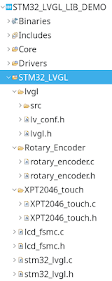
本文章介紹STM32F407VET6 使用LVGL library與結合XPT2046 touch screen 與Rotary Encoder 等input devices。
有關移植LVGL到STM32F407的步驟請參閱前篇文章
STM32 HAL|| 16 bit parallel LCD-TFT driver using FSMC interface for LVGL || DMA
詳細步驟請參閱「成果影片」
成果影片:
程式碼:
- rotary_encoder.c
/*
 * rotary_encoder.c

 */
#include <main.h>
#include "lvgl.h"

lv_indev_t *encoder_indev;
lv_group_t *encoder_group;

static TIM_HandleTypeDef *encoder_htim;

static uint32_t old_counter;

uint8_t re_key_press() {
    if (HAL_GPIO_ReadPin(Encoder_SW_GPIO_Port, Encoder_SW_Pin) == GPIO_PIN_RESET) {
        return 1;
    }
    return 0;
}

int16_t re_get_new_moves(void) {
    int16_t new_moves;
    new_moves = 0;
    uint32_t counter = __HAL_TIM_GET_COUNTER(encoder_htim);
    if (counter < old_counter) {
    	 new_moves = 1; // LV_KEY_RIGHT
    }
    if (counter > old_counter) {
    	new_moves = -1; // LV_KEY_LEFT
    }
    old_counter = counter;

    return new_moves;

}

void lvgl_encoder_read_cb(struct _lv_indev_drv_t * indev, lv_indev_data_t* data) {
  //data->key = get_key();;
	data->enc_diff = re_get_new_moves();    //rotation
	if (re_key_press()) {					// switch
		data->state = LV_INDEV_STATE_PRESSED;
	} else {
		data->state = LV_INDEV_STATE_RELEASED;
		//data->enc_diff = re_get_new_moves();
	}

 }


void lvgl_rotary_encoder_init(TIM_HandleTypeDef *htim){
	encoder_htim = htim;
	HAL_TIM_Encoder_Start(htim,  TIM_CHANNEL_1);
	__HAL_TIM_SET_COUNTER(encoder_htim,32768);
	old_counter = 32768;

	// setup rotary encoder input device
	static lv_indev_drv_t indev_drv;           /*Descriptor of a input device driver*/
	lv_indev_drv_init(&indev_drv);             /*Basic initialization*/
	indev_drv.type = LV_INDEV_TYPE_ENCODER;    /*Rotary Encoder device*/

	indev_drv.read_cb = lvgl_encoder_read_cb;      /*Set your driver function*/

	indev_drv.long_press_time=1000;
	indev_drv.long_press_repeat_time=100;
	encoder_indev = lv_indev_drv_register(&indev_drv);         /*Finally register the driver*/
	encoder_group = lv_group_create();

	//lv_group_set_default(kg);
	lv_indev_set_group(encoder_indev, encoder_group);
}
- rotary_encoder.h
/*
 * rotary_incoder.h

 */

#ifndef ROTARY_ENCODER_ROTARY_ENCODER_H_
#define ROTARY_ENCODER_ROTARY_ENCODER_H_

extern lv_indev_t *encoder_indev;
extern lv_group_t *encoder_group;

void lvgl_rotary_encoder_init(TIM_HandleTypeDef *htim);

void lvgl_encoder_read_cb(struct _lv_indev_drv_t * indev, lv_indev_data_t* data);


#endif /* ROTARY_ENCODER_ROTARY_ENCODER_H_ */
- STM32_LVGL_LIB_DEMO.ioc
#MicroXplorer Configuration settings - do not modify
CAD.formats=
CAD.pinconfig=
CAD.provider=
Dma.MEMTOMEM.0.Direction=DMA_MEMORY_TO_MEMORY
Dma.MEMTOMEM.0.FIFOMode=DMA_FIFOMODE_ENABLE
Dma.MEMTOMEM.0.FIFOThreshold=DMA_FIFO_THRESHOLD_FULL
Dma.MEMTOMEM.0.Instance=DMA2_Stream0
Dma.MEMTOMEM.0.MemBurst=DMA_MBURST_SINGLE
Dma.MEMTOMEM.0.MemDataAlignment=DMA_MDATAALIGN_HALFWORD
Dma.MEMTOMEM.0.MemInc=DMA_MINC_DISABLE
Dma.MEMTOMEM.0.Mode=DMA_NORMAL
Dma.MEMTOMEM.0.PeriphBurst=DMA_PBURST_SINGLE
Dma.MEMTOMEM.0.PeriphDataAlignment=DMA_PDATAALIGN_HALFWORD
Dma.MEMTOMEM.0.PeriphInc=DMA_PINC_ENABLE
Dma.MEMTOMEM.0.Priority=DMA_PRIORITY_LOW
Dma.MEMTOMEM.0.RequestParameters=Instance,Direction,PeriphInc,MemInc,PeriphDataAlignment,MemDataAlignment,Mode,Priority,FIFOMode,FIFOThreshold,MemBurst,PeriphBurst
Dma.Request0=MEMTOMEM
Dma.RequestsNb=1
FSMC.AddressSetupTime1=7
FSMC.BusTurnAroundDuration1=7
FSMC.DataSetupTime1=10
FSMC.IPParameters=DataSetupTime1,BusTurnAroundDuration1,AddressSetupTime1
File.Version=6
KeepUserPlacement=false
Mcu.CPN=STM32F407VET6
Mcu.Family=STM32F4
Mcu.IP0=DMA
Mcu.IP1=FSMC
Mcu.IP2=NVIC
Mcu.IP3=RCC
Mcu.IP4=SPI2
Mcu.IP5=SYS
Mcu.IP6=TIM2
Mcu.IP7=TIM3
Mcu.IPNb=8
Mcu.Name=STM32F407V(E-G)Tx
Mcu.Package=LQFP100
Mcu.Pin0=PC14-OSC32_IN
Mcu.Pin1=PC15-OSC32_OUT
Mcu.Pin10=PE7
Mcu.Pin11=PE8
Mcu.Pin12=PE9
Mcu.Pin13=PE10
Mcu.Pin14=PE11
Mcu.Pin15=PE12
Mcu.Pin16=PE13
Mcu.Pin17=PE14
Mcu.Pin18=PE15
Mcu.Pin19=PB12
Mcu.Pin2=PH0-OSC_IN
Mcu.Pin20=PB13
Mcu.Pin21=PB14
Mcu.Pin22=PB15
Mcu.Pin23=PD8
Mcu.Pin24=PD9
Mcu.Pin25=PD10
Mcu.Pin26=PD13
Mcu.Pin27=PD14
Mcu.Pin28=PD15
Mcu.Pin29=PA13
Mcu.Pin3=PH1-OSC_OUT
Mcu.Pin30=PA14
Mcu.Pin31=PD0
Mcu.Pin32=PD1
Mcu.Pin33=PD4
Mcu.Pin34=PD5
Mcu.Pin35=PD7
Mcu.Pin36=VP_SYS_VS_Systick
Mcu.Pin37=VP_TIM3_VS_ClockSourceINT
Mcu.Pin4=PA0-WKUP
Mcu.Pin5=PA1
Mcu.Pin6=PA5
Mcu.Pin7=PC4
Mcu.Pin8=PC5
Mcu.Pin9=PB1
Mcu.PinsNb=38
Mcu.ThirdPartyNb=0
Mcu.UserConstants=
Mcu.UserName=STM32F407VETx
MxCube.Version=6.12.0
MxDb.Version=DB.6.0.120
NVIC.BusFault_IRQn=true\:0\:0\:false\:false\:true\:false\:false\:false
NVIC.DebugMonitor_IRQn=true\:0\:0\:false\:false\:true\:false\:false\:false
NVIC.ForceEnableDMAVector=true
NVIC.HardFault_IRQn=true\:0\:0\:false\:false\:true\:false\:false\:false
NVIC.MemoryManagement_IRQn=true\:0\:0\:false\:false\:true\:false\:false\:false
NVIC.NonMaskableInt_IRQn=true\:0\:0\:false\:false\:true\:false\:false\:false
NVIC.PendSV_IRQn=true\:0\:0\:false\:false\:true\:false\:false\:false
NVIC.PriorityGroup=NVIC_PRIORITYGROUP_4
NVIC.SVCall_IRQn=true\:0\:0\:false\:false\:true\:false\:false\:false
NVIC.SysTick_IRQn=true\:15\:0\:false\:false\:true\:false\:true\:false
NVIC.TIM3_IRQn=true\:0\:0\:false\:false\:true\:true\:true\:true
NVIC.UsageFault_IRQn=true\:0\:0\:false\:false\:true\:false\:false\:false
PA0-WKUP.Signal=S_TIM2_CH1_ETR
PA1.Signal=S_TIM2_CH2
PA13.Mode=Serial_Wire
PA13.Signal=SYS_JTMS-SWDIO
PA14.Mode=Serial_Wire
PA14.Signal=SYS_JTCK-SWCLK
PA5.GPIOParameters=GPIO_PuPd,GPIO_Label
PA5.GPIO_Label=Encoder_SW
PA5.GPIO_PuPd=GPIO_PULLUP
PA5.Locked=true
PA5.Signal=GPIO_Input
PB1.GPIOParameters=GPIO_Label
PB1.GPIO_Label=LCD_BL
PB1.Locked=true
PB1.Signal=GPIO_Output
PB12.GPIOParameters=GPIO_Label
PB12.GPIO_Label=T_CS
PB12.Locked=true
PB12.Signal=GPIO_Output
PB13.Locked=true
PB13.Mode=Full_Duplex_Master
PB13.Signal=SPI2_SCK
PB14.Locked=true
PB14.Mode=Full_Duplex_Master
PB14.Signal=SPI2_MISO
PB15.Locked=true
PB15.Mode=Full_Duplex_Master
PB15.Signal=SPI2_MOSI
PC14-OSC32_IN.Mode=LSE-External-Oscillator
PC14-OSC32_IN.Signal=RCC_OSC32_IN
PC15-OSC32_OUT.Mode=LSE-External-Oscillator
PC15-OSC32_OUT.Signal=RCC_OSC32_OUT
PC4.Locked=true
PC4.Signal=GPIO_Input
PC5.GPIOParameters=GPIO_Label
PC5.GPIO_Label=T_IRQ
PC5.Locked=true
PC5.Signal=GPIO_Input
PD0.Mode=16b-d1
PD0.Signal=FSMC_D2
PD1.Mode=16b-d1
PD1.Signal=FSMC_D3
PD10.Mode=16b-d1
PD10.Signal=FSMC_D15
PD13.Mode=A18_1
PD13.Signal=FSMC_A18
PD14.Mode=16b-d1
PD14.Signal=FSMC_D0
PD15.Mode=16b-d1
PD15.Signal=FSMC_D1
PD4.Mode=Lcd1
PD4.Signal=FSMC_NOE
PD5.Mode=Lcd1
PD5.Signal=FSMC_NWE
PD7.Mode=NorPsramChipSelect1_1
PD7.Signal=FSMC_NE1
PD8.Mode=16b-d1
PD8.Signal=FSMC_D13
PD9.Mode=16b-d1
PD9.Signal=FSMC_D14
PE10.Mode=16b-d1
PE10.Signal=FSMC_D7
PE11.Mode=16b-d1
PE11.Signal=FSMC_D8
PE12.Mode=16b-d1
PE12.Signal=FSMC_D9
PE13.Mode=16b-d1
PE13.Signal=FSMC_D10
PE14.Mode=16b-d1
PE14.Signal=FSMC_D11
PE15.Mode=16b-d1
PE15.Signal=FSMC_D12
PE7.Mode=16b-d1
PE7.Signal=FSMC_D4
PE8.Mode=16b-d1
PE8.Signal=FSMC_D5
PE9.Mode=16b-d1
PE9.Signal=FSMC_D6
PH0-OSC_IN.Mode=HSE-External-Oscillator
PH0-OSC_IN.Signal=RCC_OSC_IN
PH1-OSC_OUT.Mode=HSE-External-Oscillator
PH1-OSC_OUT.Signal=RCC_OSC_OUT
PinOutPanel.RotationAngle=0
ProjectManager.AskForMigrate=true
ProjectManager.BackupPrevious=false
ProjectManager.CompilerOptimize=6
ProjectManager.ComputerToolchain=false
ProjectManager.CoupleFile=false
ProjectManager.CustomerFirmwarePackage=
ProjectManager.DefaultFWLocation=true
ProjectManager.DeletePrevious=true
ProjectManager.DeviceId=STM32F407VETx
ProjectManager.FirmwarePackage=STM32Cube FW_F4 V1.28.0
ProjectManager.FreePins=false
ProjectManager.HalAssertFull=false
ProjectManager.HeapSize=0x200
ProjectManager.KeepUserCode=true
ProjectManager.LastFirmware=false
ProjectManager.LibraryCopy=1
ProjectManager.MainLocation=Core/Src
ProjectManager.NoMain=false
ProjectManager.PreviousToolchain=
ProjectManager.ProjectBuild=false
ProjectManager.ProjectFileName=STM32_LVGL_LIB_DEMO.ioc
ProjectManager.ProjectName=STM32_LVGL_LIB_DEMO
ProjectManager.ProjectStructure=
ProjectManager.RegisterCallBack=
ProjectManager.StackSize=0x400
ProjectManager.TargetToolchain=STM32CubeIDE
ProjectManager.ToolChainLocation=
ProjectManager.UAScriptAfterPath=
ProjectManager.UAScriptBeforePath=
ProjectManager.UnderRoot=true
ProjectManager.functionlistsort=1-SystemClock_Config-RCC-false-HAL-false,2-MX_GPIO_Init-GPIO-false-HAL-true,3-MX_DMA_Init-DMA-false-HAL-true,4-MX_FSMC_Init-FSMC-false-HAL-true,5-MX_SPI2_Init-SPI2-false-HAL-true,6-MX_TIM2_Init-TIM2-false-HAL-true,7-MX_TIM3_Init-TIM3-false-HAL-true
RCC.48MHZClocksFreq_Value=48000000
RCC.AHBFreq_Value=168000000
RCC.APB1CLKDivider=RCC_HCLK_DIV4
RCC.APB1Freq_Value=42000000
RCC.APB1TimFreq_Value=84000000
RCC.APB2CLKDivider=RCC_HCLK_DIV2
RCC.APB2Freq_Value=84000000
RCC.APB2TimFreq_Value=168000000
RCC.CortexFreq_Value=168000000
RCC.EthernetFreq_Value=168000000
RCC.FCLKCortexFreq_Value=168000000
RCC.FamilyName=M
RCC.HCLKFreq_Value=168000000
RCC.HSE_VALUE=8000000
RCC.HSI_VALUE=16000000
RCC.I2SClocksFreq_Value=192000000
RCC.IPParameters=48MHZClocksFreq_Value,AHBFreq_Value,APB1CLKDivider,APB1Freq_Value,APB1TimFreq_Value,APB2CLKDivider,APB2Freq_Value,APB2TimFreq_Value,CortexFreq_Value,EthernetFreq_Value,FCLKCortexFreq_Value,FamilyName,HCLKFreq_Value,HSE_VALUE,HSI_VALUE,I2SClocksFreq_Value,LSI_VALUE,MCO2PinFreq_Value,PLLCLKFreq_Value,PLLM,PLLN,PLLQ,PLLQCLKFreq_Value,PLLSourceVirtual,RTCFreq_Value,RTCHSEDivFreq_Value,SYSCLKFreq_VALUE,SYSCLKSource,VCOI2SOutputFreq_Value,VCOInputFreq_Value,VCOOutputFreq_Value,VcooutputI2S
RCC.LSI_VALUE=32000
RCC.MCO2PinFreq_Value=168000000
RCC.PLLCLKFreq_Value=168000000
RCC.PLLM=4
RCC.PLLN=168
RCC.PLLQ=7
RCC.PLLQCLKFreq_Value=48000000
RCC.PLLSourceVirtual=RCC_PLLSOURCE_HSE
RCC.RTCFreq_Value=32000
RCC.RTCHSEDivFreq_Value=4000000
RCC.SYSCLKFreq_VALUE=168000000
RCC.SYSCLKSource=RCC_SYSCLKSOURCE_PLLCLK
RCC.VCOI2SOutputFreq_Value=384000000
RCC.VCOInputFreq_Value=2000000
RCC.VCOOutputFreq_Value=336000000
RCC.VcooutputI2S=192000000
SH.S_TIM2_CH1_ETR.0=TIM2_CH1,Encoder_Interface
SH.S_TIM2_CH1_ETR.ConfNb=1
SH.S_TIM2_CH2.0=TIM2_CH2,Encoder_Interface
SH.S_TIM2_CH2.ConfNb=1
SPI2.BaudRatePrescaler=SPI_BAUDRATEPRESCALER_32
SPI2.CalculateBaudRate=1.3125 MBits/s
SPI2.Direction=SPI_DIRECTION_2LINES
SPI2.IPParameters=VirtualType,Mode,Direction,CalculateBaudRate,BaudRatePrescaler
SPI2.Mode=SPI_MODE_MASTER
SPI2.VirtualType=VM_MASTER
TIM2.EncoderMode=TIM_ENCODERMODE_TI1
TIM2.IC1Filter=0
TIM2.IC1Polarity=TIM_ICPOLARITY_FALLING
TIM2.IC2Filter=0
TIM2.IC2Polarity=TIM_ICPOLARITY_FALLING
TIM2.IPParameters=Period,IC2Polarity,IC1Polarity,EncoderMode,Prescaler,IC1Filter,IC2Filter
TIM2.Period=65535
TIM2.Prescaler=0
TIM3.IPParameters=Prescaler,Period
TIM3.Period=10-1
TIM3.Prescaler=42000-1
VP_SYS_VS_Systick.Mode=SysTick
VP_SYS_VS_Systick.Signal=SYS_VS_Systick
VP_TIM3_VS_ClockSourceINT.Mode=Internal
VP_TIM3_VS_ClockSourceINT.Signal=TIM3_VS_ClockSourceINT
board=custom
isbadioc=false
其餘程式碼請參閱前篇文章:
